Table of Contents
This page has deprecated and will be archived. Please go to https://www.bitcraze.io/.
Crazyflie KIT electronics explained
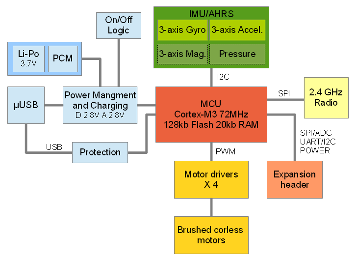
This section is here to explain all high level electronics used in the Crazyflie.
Electronics overview
Battery
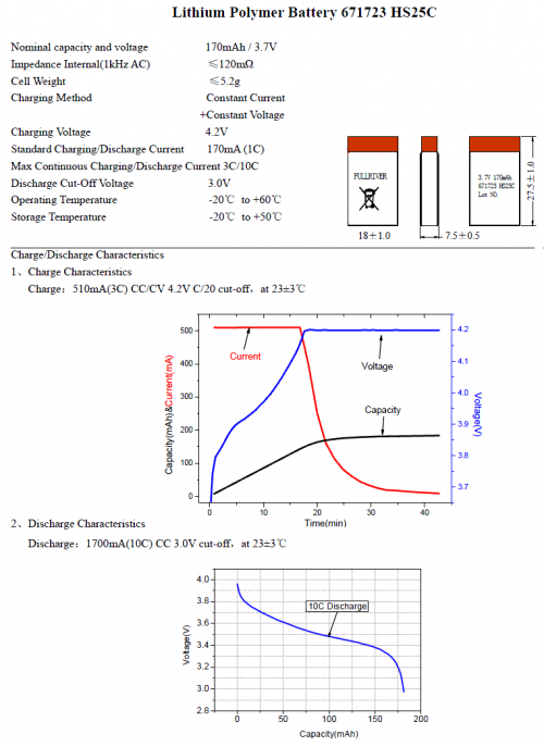
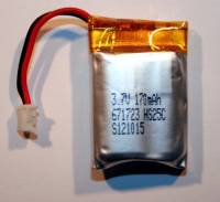 The battery we use is of the type LiPo (Lithium-Polymer). They are currently the most popular battery type for R/C use. The LiPo is however not the safest chemistry and should be handled with care. Failing to do so could make it catch on fire. It is also sensitive to under/over charge, to high discharge/shortage, heat and more. What it is good at however compensates for all these shortcomings as it has among the best power to weight ratios and discharge currents.
PCM
To handle some of the LiPo shortcomings we use a PCM (Protection Circuit Module) that will prevent the user from under/over charging or shorting it. The PCM is located under the orange tape on the top side of the battery where the wires come out.
The PCM has the following spec:
| Item | Specification | ||
| Overcharge detection voltage | 4.20±0.025V | ||
| Overcharge release voltage | 4.10±0.050V | ||
| Overcharge detection delay time | 0.92~1.38S | ||
| Over discharge detection voltage | 2.80±0.050V | ||
| Over discharge release voltage | 2.90±0.100V | ||
| Over discharge detection delay time | 115~173 ms | ||
| Over discharge current | 4~9A | ||
| Over discharge current delay time | 7.2~11ms | ||
| Short detection delay time | 220~380us | ||
| Short release condition | Cut off load | ||
| Current consumption | Max 0.7uA | ||
| Suggested max continuous charge/discharge current | 3A | ||
| Suggested operation temp | -20 - +60 deg C | ||
| Internal resistance | <60mOhm |
LiPo
The LiPo used is the 671723HS25C from Fullriver.
Specification:
| Model | Voltage (V) | Capacity (mAh) | Thickness (±0.2) | Width (±0.5) | Height (±0.5) | Weight (g) | Charge Rate | Continuous Discharge Rate | Burst (≤5S) | ||||||||||
| 671723HS25C | 3.7 | 170 | 6.9 | 17 | 23 | 3.9 | 1C-5C | 25C (≥ 80%) | 50C |
Connector
The connector we use is on the battery side is the JST-ZHR-2P. It can according to it's specification only handle 1A continuously but we have tested several connectors at 4A with no sign of any problem. The contact resistance we measured was 4mOhm so we choose to use this connector even though we consume ~1.4A at hover and lots more during bursts.
Replacing
It is possible to replace the battery with another LiPo to get longer flight times or make it lighter. Best would be to fit the new LiPo with the same connector, it is common and can be bought at most distributors, or one could remove the connector on the PCB and solder it directly to the board. If you choose to replace the battery make sure it has a PCM and choose one with a high discharge rate.
We have tested several sizes of LiPo batteries, 100mAh to 400mAh, and found out that 150mAh to 250mAh is the sweet spot giving the best flight performance.
Power
Power management
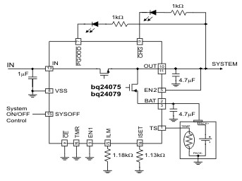 The power management is mainly handled by the TI BQ24075 power management chip. It handles on/off and charging of LiPo. The BQ24075 has three input limiting modes, 100mA, 500mA and user selectable (currently set to 740mA) which makes it easier to comply to USB standard. It also makes it possible to quick charge if the Crazyflie is connected to a wall adapter. However our 170mAh battery should normally not charge faster then 3C (510mA).
Power distribution
The Crazyflie control board utilizes the separate power plane technique using a 4 layer board. It has proven to work pretty well and we have low ripple currents. However it is not perfect and at some Radio channels we can notice that the motor PWM sometimes is interfering with the Radio.
There are a number of supplies and grounds
| Supply | Range (V) | Description | |||
| +BATT | 3.0 - 4.2 | Battery supply voltage | |||
| VCOM | 3.0 - 5.5 | Supply after power management chip. Can be +BATT or USB voltage | |||
| VCC | 2.8 or 3.3 | Digital supply voltage. Input is the VCOM supply | |||
| VCCA | 2.8 | Analog supply voltage, which is filtered. Input is the VCOM supply | |||
| GND | 0 | The ground shared by the motor drivers and the battery | |||
| DGND | 0 | Digital ground. Connected to GND in a start-point fashion. | |||
| AGND | 0 | Analog ground. Connected to GND in a start-point fashion. |
The analog and digital supply uses the TPS79301 adjustable voltage regulator. It is a ultra-low noise 200 mA capable LDO voltage regulator. We choose to use the adjustable variant for both supplies to have maximum tune-ability. This way one can set the output voltage just by changing a couple of resistors. It has also enabled us to make the digital supply switch from 2.8 V to 3.3 V when the micro-USB cable is connected so we can comply the the USB standard.
MCU
The MCU (Micro Controller Unit) we use, the brain of the Crazyflie, is the ST Microelectronics STM32F103CB. We actually choose this MCU in 2009 and now it is very commonly used by hobbyists and other UAV platforms. The STM32F103CB MCU we run at full speed, 70Mhz, and it has 128Kb flash and 20Kb RAM. As of December 2012 our current firmware takes 46kb flash and 16kb RAM. The RAM can definitely be more optimised so there are plenty of room to implement more algorithms and fun stuff. We use about 40% of its processing power (with a stabilization update loop at 500Hz) and a big chunk of this is because we use a “blocking” I2C driver.
Sensors
As for sensors we run a “6-axis” system using the MPU-6050 from Invensense which contains a 3-axis gyroscope and an 3-axis accelerometer in a single chip. This is enough to “attitude” stabilize the Crazyflie making it self levelling. Our first versions used the analogue variants IDG500 and ISZ500 but the gyro in the MPU-6050 preforms better. The accelerometer in the MPU-6050 however does not perform as well as the Bosch BMA145 we used before but is adequate. The MPU-6050 does not reject the high frequency vibrations as well as the BMA145 therefore keeping the vibration from the motors/props to a minimum makes a big different performance wise.
With a 6-axis system it is not possible to remove the yaw drift and for an autonomous system this could important. Therefore it is possible to manually solder-mount an magnetometer HMC5883L/HMC5983 afterwards (we have not tested the HMC5983 yet, dec-2012). However we have not put to much time into testing the Crazyflie with a magnetometer and due to the strong magnet fields from the close-by motors it could be a challenge.
It is also possible to manually solder-mount a MS5611 pressure sensor afterwards if that is of interest. This could make it possible add an altitude-hold functionality. No SW support now though.
Expansion header
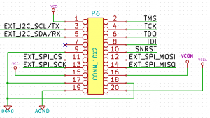 The expansion header is located on the left side of the Crazyflie. It is a 10×2 pin 1.27mm (0.05“) pitch through-hole footprint which comes unmounted. The idea with the through-hole is that it makes it possible to mount expansion boards on either, or both, sides. It would even be possible to stack several on top of each other.
The header is divided into two parts. The JTAG part, pin 1 to 10, and the buss/power part, pin 11 to 20. The UART RX/TX is located on the JTAG part because on many FTDI based JTAGs it is possible to use one channel for serial communication which can be very handy when debugging.
Header pin description
| Pin nr | Name | Description | |||
|---|---|---|---|---|---|
| 1 | VCC | Digital supply voltage | |||
| 2 | TMS | Test Mode Select | |||
| 3 | EXT_I2C_SCL/TX | I2C clock or UART TX | |||
| 4 | TCK | Test Clock | |||
| 5 | EXT_I2C_SDA/RX | I2C data or UART RX | |||
| 6 | TDO | Test Data Out | |||
| 7 | N/A | Could be used for keying | |||
| 8 | TDI | Test Data In | |||
| 9 | DGND | Digital ground | |||
| 10 | SNRST | System reset | |||
| 11 | EXT_SPI_CS/AIN4 | SPI chip select or analogue in 4 | |||
| 12 | EXT_SPI_MOSI/AIN7 | SPI Master Out Slave In chip or analogue in 7 | |||
| 13 | EXT_SPI_SCK/AIN5 | SPI clock or analogue in 5 | |||
| 14 | EXT_SPI_MISO/AIN6 | SPI Master In Slave Out chip or analogue in 6 | |||
| 15 | VCC | Digital supply voltage | |||
| 16 | VCOM | Battery/USB voltage | |||
| 17 | DGND | Digital ground | |||
| 18 | DGND | Digital ground | |||
| 19 | AGND | Analogue ground | |||
| 20 | VCCA | Analogue supply |
2.4GHz radio
Motor drivers
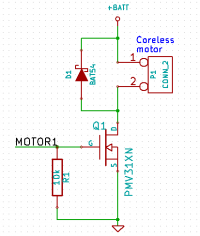 The motor driver, as we use brushed motors, is a simple pull down mosfet as shown in the schematics. There is also a free-wheel diode to take the Back-EMF spikes generated by the motor during PWM-ing.
The mosfet we choose is the PMV31XN in a SOT-23 package. It can handle a lot of power and should be good for at least 3A each. The most important property of the mosfet though might be the on resistance (Rdson) since it effects the amount of power the motors can make use of. We measured the PMV31XN Rdson at 2.8V G-D voltage and 0.8A D-S current to be ~40 mOhm.
Motors
We use a coreless brushed DC motor 6x15mm.
Specification
Electrical
| Description | Value | ||
| Rated voltage | 4.2 V Max | ||
| Nominal voltage | 3.7 V | ||
| No load speed | 45000 ±15% RPM | ||
| No load current | 80 mA Max | ||
| Starting voltage | 0.8 V Max | ||
| Rated load speed | 21000 ±15% RPM | ||
| Rated load current | 810 mA Max | ||
| Resistance | 2.3 ±20% Ω |
Mechanical
| Description | Value | ||
| Shaft diameter | 0.8 mm | ||
| Motor diameter | 6 ± 0.05 mm | ||
| Motor length | 15 mm | ||
| Weight | 1.7 g approx. |
