Products
-
-
- Accessories
- Breakout boards
This is an old revision of the document!
IMPORTANT
We're currently working on updating the documentation for the Loco positioning system. Until the documentation is completed you can find the early access documentation here.
The Loco Positioning system (LPS) project is a set of hardware and software designed to implement a local positioning system (LPS). Current hardware comprises one LPS Node and one LPS Deck. Both are based on the Decawave DWM1000 chip.
The local positioning system is based on the DecaWave DWM1000 module. The system consists of a number of anchors that are continuously pinged from the Crazyflie 2.0 deck that's based on the same module. The anchors are placed around the room at known positions.
The system supports a number of different modes:
This getting started documentation is intended to guide you from receiving your Loco Positioning Indoor Explorer Bundle to having an autonomous Crazyflie 2.0.
For working with the Loco positioning system there's a variety of tools available:
It is also possible to script movements using the Crazyflie Python Library (example)
In order to illustrate how to set up a system we document a reference system and how we've set it up. The referance system is based on the Indoor explorer bundle which contains the following:
The Kalman filter used position Crazyflie in the LPS is not yet part of the default firmware so you need to compile the Crazyflie firmware with Kalman support activated. Clone or pull the latest version from Github and put the following lines in your tools/make/config.mk:
ESTIMATOR = kalman
Compile and flash the Crazyflie:
make clean
make
make cload
For “make cload” to work, you need to have the Crazyflie client cloned and installed in the same folder as the Crazyflie firmware.
Use the LPS configuration tool to update the firmware and set the addresses of the nodes from 0-5. Note the address on the nodes.
The nodes should be placed at least 15 cm away from walls or ceiling. In our reference set-up we accomplish this by using these 3D printed stands.
Power the anchors with 5V using either the micro-USB connector, the terminal or the DJ-jack.
Note; If you're not following our reference set-up for placing the nodes try to space them out at lest 2 meters apart and at different heights (see Dilution Of Precision).
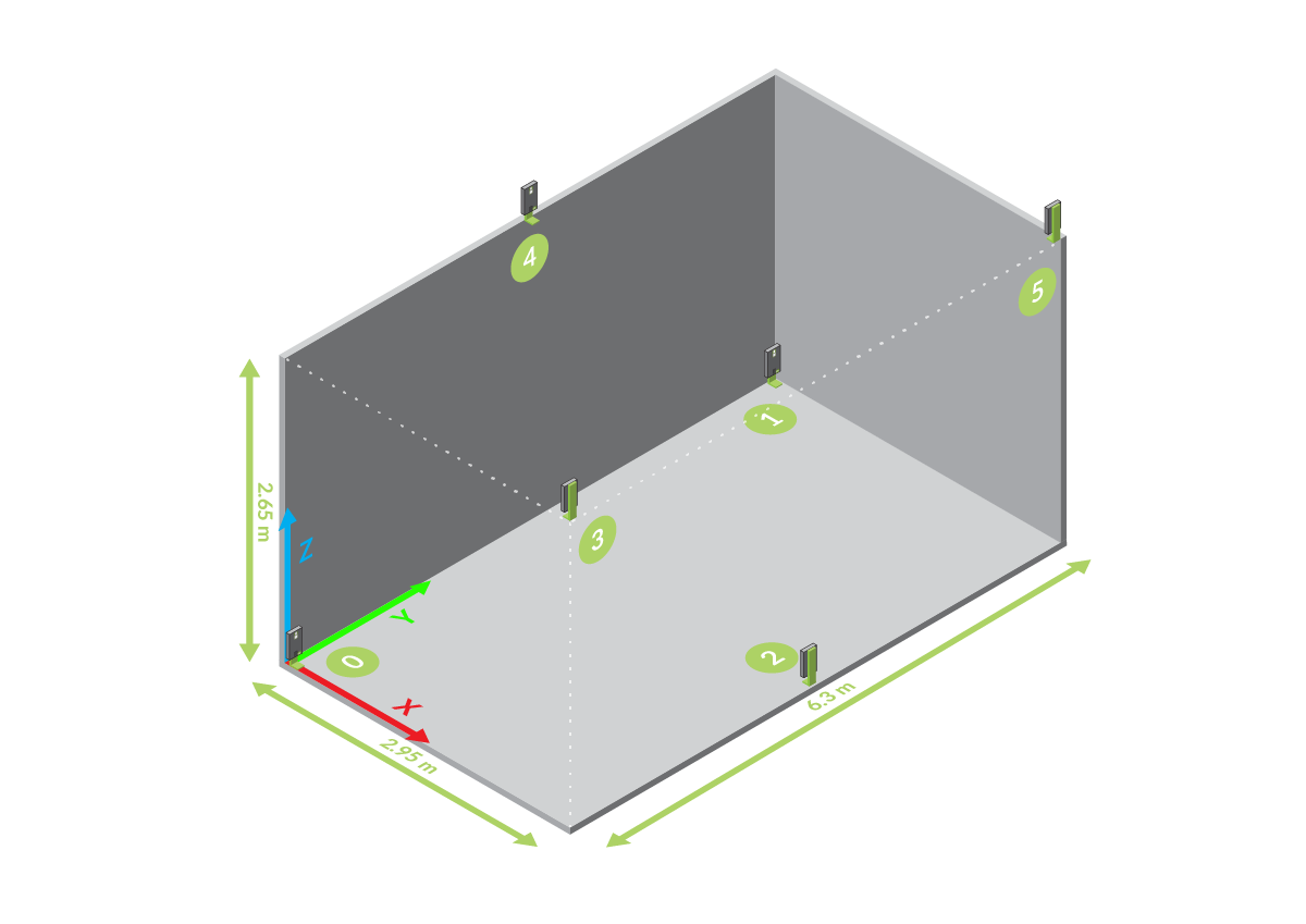
The position in X/Y/Z of the anchor UWB antenna needs to be measured. To do so chose an origin (in a square/rectangular room one of the corners is a good choice), choose your axis to be a right-handed coordinates. Finally you can measure the X/Y/Z position of the anchors in this coordinate system. Using a corner as origin means that you can use a laser-ranger against the walls to get a direct reading of the coordinates.
Use the LPS tab of the Crazyflie client to store the physical anchor positions in the anchors. The communication from the client to the anchors is bridged through a Crazyflie, so you must have a Crazyflie with an Loco Positioning deck connected to the client.
In our reference setup we have placed 3 anchors above and 3 anchors bellow the flight area, shaped in inverse triangles. This allows to get good accuracy in X, Y and Z.
This is the reference system from which measurement where taken:

The Loco Positioning tab in the PC-client is used to set the anchor positions, validate anchor positions and to verify that the estimated position is reasonable.
To validate the system we took a series of measurement from the reference system. You can see the results in the page Measurements of accuracy and precision of the Loco Positioning system.