User Tools

Site Tools


projects:bolt:index

The Crazyflie Bolt is currently part of our early access program. To better understand what this means also have a look at our Product cycle.

Crazyflie Bolt

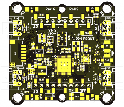
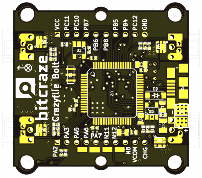
The Crazyflie Bolt is a Crazyflie 2.X compatible flight controller for brushless builds. It is intended to have the strengths of the Crazyflie 2.1, but in a slightly bit bigger package.

Board renderings

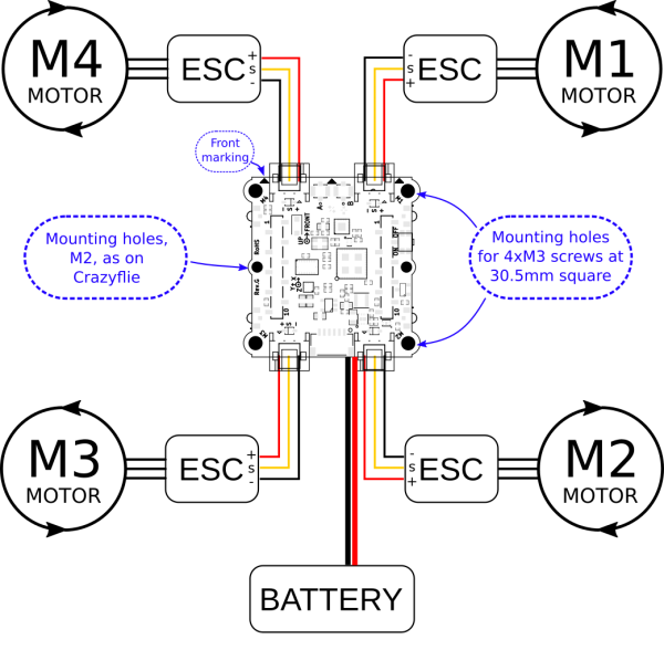
The size of the board is 36mm x 35.4mm and the holes are M3, located at the common 30.5mm square, to fit most frames.

Specification

Please see the shop product page for full specification.

Features and differences from Crazyflie 2.1

  • Fully compatible with the CF2 firmware, expansion decks as well as radio.
  • 4 x connectors to attach motor controllers (also possible to solder) so it is easy to build and repair.
  • Power distributions built into controller board. (Max ~8A per motor controller) with XT30 connector.
  • Motor controllers can be switched off by the system (MOSFET) so the system can go into deep sleep and only consume around 50uA.
  • Voltage input 1S-4S (3V to 17V).
  • External antenna for increased range with possibility to use diverisy (two antennas).
  • SPI connected IMU (BMI088) for minimum latency.
  • Not using any deck expansion pins as the Big-quad deck does
  • Can run brushed motors as well
  • Can measure battery voltage (but not current)
  • Can be powered from external 5V as well when using external PDB

Power

The Bolt contains a power distribution board (PDB) but it is a bit limiting. The current has to pass a MOSFET, to be able to switch it off, and also the ESC connector. We have tested running 8A though the chain without any limiting heat-up, but that is as far as we would recommend to go. If additional current is wanted, one could bypass the connectors by soldering the ESC directly to the connector soldering pad. The MOSFET is still there but a slight increase should be possible. For higher currents, an external PDB should be used. Other tricks to keep current down, but power up, is to run on higher voltage (3S or 4S) and using low KV motors.

Schematics

General setup

A bigger quadrotor is dangerous so make sure to be SAFE!

  • To not exceed the 8A / ESC connector output the battery voltage, motor and propeller should be selected so this does not happen. The ESC can be rated higher as it does not noticeably effect current draw, only efficiency.
  • Preferably select a frame so decks can be attached. It is hard to make e.g. the flow v2 deck and lighthouse deck work at the same time as the battery needs to be placed somewhere, which is normally in the center, above or below the Bolt control board.
  • 4in1 ESCs can be convenient but for the Bolt it is often better to use 4 separate ESC mounted on the arms as this frees up space for decks.
  • If higher then 8A is wanted only connect the signal wires from the ESC connectors to the ESC. Preferably still power the Bolt control board via the battery connector so the battery voltage can be monitored.

Example setup

Configuration

The Crazyflie firmware will automatically detect that it is running on a Bolt and activate the right modules. However some of the configurations still has to be done during compile time and making them run time configurable is currently work in progress.

Current firmware status notes (2019-10)

  • Different PID tuning parameters might be needed for it to fly well. Currently this has to be hard coded. Later this will be saved in the EEPROM or in the 1-wire memory.
  • External battery voltage/current reading is implemented but no logic behind it, so don't run out of battery.
  • The ESC PWM output is set by default to 400Hz. Use ESCs which can handle this or compile with new value. There is also the possibility to enable OneShot125 output.
  • It is wise to do a range test before flying far away.
  • Be safe, it is experimental software. Run all testing without props!
projects/bolt/index.txt · Last modified: 2019-12-09 15:17 by tobias