
Products
-
-
- Accessories
- Breakout boards
This is an old revision of the document!
The BigQuad deck is currently part of our early access program. To better understand what this means also have a look at our Product cycle.
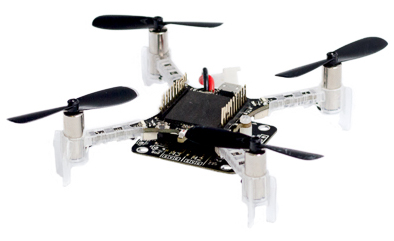
With the BigQuad deck you can transform your Crazyflie 2.0 to a bigger quad by connecting external ESCs (Electronic Speed Controller) to the breakout connectors on the deck. The autodetection of the deck makes this transformation possible to do in seconds. The deck contains breakout header connectors for additional accessories such as external receiver (CPPM input) and GPS. It also has the possibility to monitor battery voltage and current.
The deck is designed to be installed either on the top or the bottom of the Crazyflie.
Drivers for the BigQuad are integrated in the Crazyflie 2.0 firmware.

Electrical specification:
Mechanical specification:
Package contents:
BigQuad expansion deck schematic.
 The Loco deck, microSD and Flow (v2) deck all uses the SPI bus. As the BigQuad deck uses the deck SPI buss pins for possible voltage and current measurement, and they are multiplexed with analog input, the BigQuad deck is not out-of-the-box compatible with these decks. This can fixed:
Capacitor C1 is used to filter the current measurement and removing this has the effect that it will not be filtered any more. Still possible to use it if a deck using the SPI is not wanted any more.
To make it work with the Flow (v2) deck more changes/patching are needed.
Next problem is how to mount the deck in a nice way on the quad, we leave that up to you.
Currently there is only a basic setup but as the development advances so will the documentation. Start by mounting the big quad deck on the frame. After that connect the ESCs according to the diagrams below.
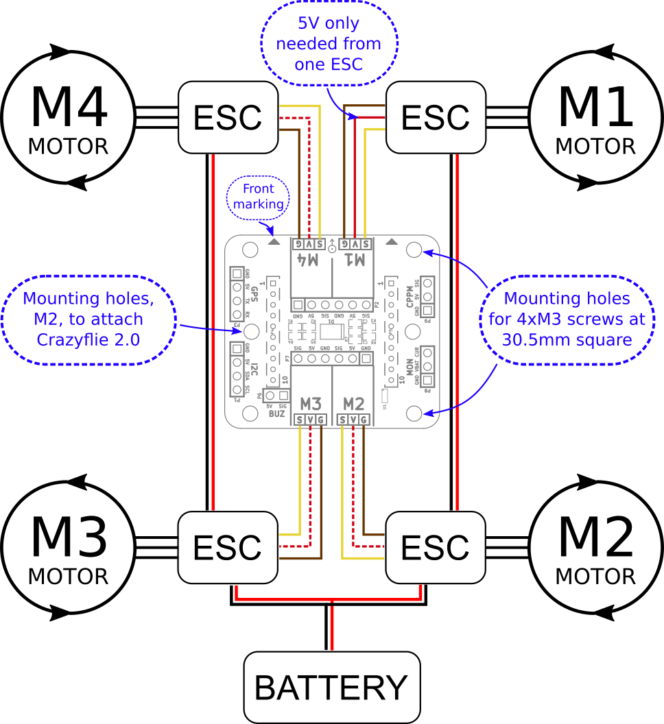
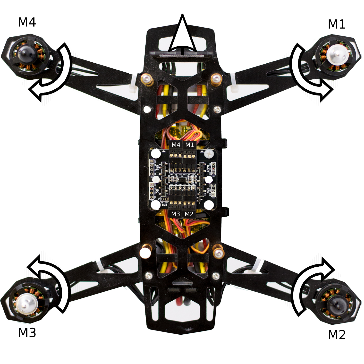
The front of the Crazyflie 2.0 should be pointing in the direction of the arrows (front) on the BigQuad deck.
If the frame allows it, the Crazyflie 2.0 motors can be kept mounted but it is fine to remove them as well. Attach and connect the Crazyflie 2.0 using either the long or short deck pins. Use the included nylon spacer and screws to secure the Crazyflie 2.0 in place and to keep it level.
The BigQuad deck contains a 1-wire memory so it can be automatically detected and functions initialized. However as this currently is an ongoing development and a bigger quads ads a new level of caution we have decided to not enable the functionality by default. Therefore the firmware needs to be compiled with the ENABLE_BQ_DECK flag enabled.
Make sure to have the crazyflie-firmware code updated to a later version then this commit. Then define the flag ENABLE_BQ_DECK, preferably in the config.mk file add
CFLAGS += -DENABLE_BQ_DECK
Clean and build the firmware and flash it using you preferred method. Now when the Crazyflie 2.0 is started and it is connected to the BigQuad deck it will start outputting PWM signals to the ESC connectors. The motors will not spin during the Crazyflie 2.0 power on self-test (POST).
