
Products
-
-
- Accessories
- Breakout boards
This is an old revision of the document!
This page is intended to give an overview on how to use the Crazyflie client, not for installing it. For install instructions go here.
The Crazyflie client is used for controlling the Crazyflie, flashing firmware, setting parameters and logging data. The main UI is built up of a number of tabs, where each tab is used for a specific functionality.
This page uses the terms roll/pitch/yaw extensively. For that to make any sense for a quadcopter we need to know where the front is (Crazyflie 1.0, Crazyflie 2.0).
Once you have connected to the Crazyflie you can just use the Quick connect button next time you start the application.
For more info on LED indicators etc. have a look at the Crazyflie or Crazyflie 2.0 user guide.

Below are a few guides on how to accomplish specific tasks with the client.
There's two ways to connect to a Crazyflie, either by searching for Crazyflies and selecting one or by directly connecting to the previously connected one. Either two options are available from the menus (Crazyflie→Connect to Crazyflie or Crazyflie→Quick connect) or directly from the toolbar (details). For more information on the Crazyflie URIs show in the list have a look here.
If you search for Crazyflies the following dialog will be shown:

For updating the Crazyflie firmware there's the possibility to enter bootloader mode and flash new firmware from within the client. The bootloader mode is accessed from the menu Crazyflie→Bootloader. If there is any problem during the flashing or a wrong firmware is flashed the process can just be started again.
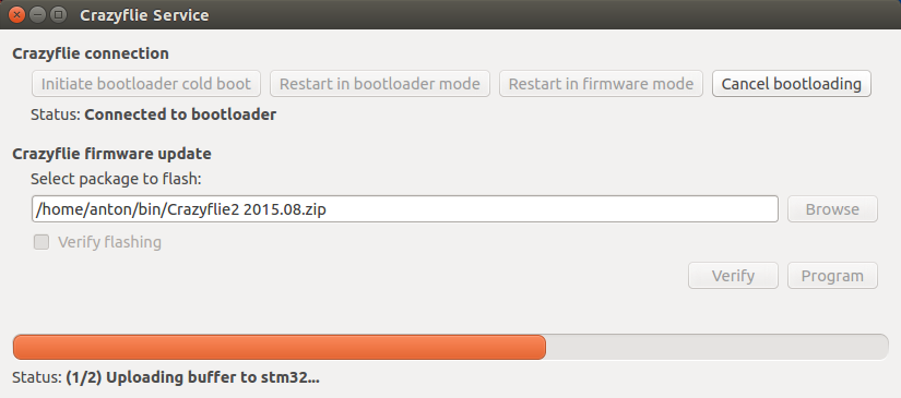
To update the firmware in the Crazyflie 1.0/2.0 do the following:
To check the firmware version, under the View menu, open up Tabs→Console tab and look at the output when connecting to the Crazyflie 1.0/2.0.
It is possible to set another channel to communicate with the Crazyflie 1.0/2.0. It can be wise to do this if there exist other wireless networks that can interfere, especially WiFi. It is also possible to permanently store the trim values for pitch and roll.
It is currently possible to change the following parameters which are stored in a none volatile memory:
The procedure is described below and the parameters can be changed again any time the same way.
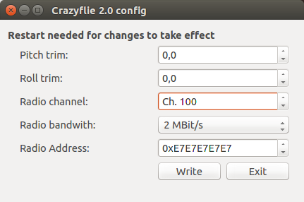
| Crazyflie 1.0 | Crazyflie 2.0 | |
| Click on the menu “Crazyflie→Configure 1.0” and then connect the bootloader by clicking on the “cold boot” button and by restarting the Crazyflie. | First connect to the Crazyflie 2.0 with the normal connect button. Then open “Crazyflie→Configure 2.0” to reach the configure 2.0 dialog | |
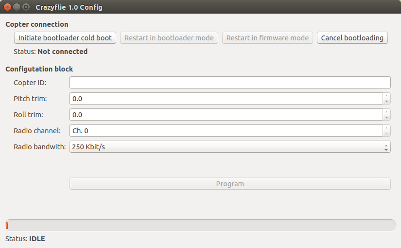 |  |
|
| Once the settings has been made press the program button to save them permanently in the Crazyflie flash. | Once the settings has been made press the write button to save them permanently in the Crazyflie 2.0 EEPROM. | |
TODO
By using the settings on the Flight control tab you can set things such as the max roll/pitch and thrust.
In order to control the Crazyflie you are connected to you will need some input-device. Normally this would be a gamepad, but any input-device with at least 4 analog axis will do. Here's a list of some input-devices that are used.
In order to make sense of the input from the device a mapping has to be supplied. This mapping will convert raw axis values on the input-device to useful values like roll/pitch/yaw/thrust. There's a few default mappings shipped with the client, but it's easy to create your own.
The software comes bundled with mappings for Xbox and PS3/4 controllers, but if you have another input-device then it's quick to create your own configuration. Go to the menu Input device → Configure device mapping.

Select the device you would like to configure and press Configure.

For each functionality that can be mapped there's a Detect button, by pressing it the following dialog will appear.

Follow the instructions to detect the axis or button that you would like to map to the functionality. If you would like to map the functionality to two axis (like right/left solder-button) then select Combined axis detection and follow the instructions.
Go though all the functionality you would like to map by pressing the Detect button for each. To be able to save the mapping you will at least have to map roll, pitch, yaw and thrust.

Once you have mapped functionality you will be able to see the feedback directly in the configuration dialog (when you're not detecting a button). Make sure to check that the response is what you intended. When you are finished with the mapping then enter the map name and press save.
If you would like to start from a previous configuration and change it (either to update or to create a new one) then select the appropriate mapping in the drop-down and press Load. Once you have made the changes you would like to do then either press Save without changing the name to update the mapping or enter a new name and press Save to create a new one.
The current input device and mapping can be selected from the Input device menu.
The Input device menu contains a number of different “modes” that can be used for controlling a Crazyflie. Currently there's thee to choose from. The alternatives will only be enabled if there's enough input devices connected to use them.
For normal usage just enter the Normal menu, select the device you would like to use and the correct mapping. As a device is selected the list of mappings are enabled.

If more than one input device is connected then it's possible to switch to one of the teacher modes.

First select the device that should be used for the teacher and then it's mapping.

Then select the device that should be used for the student and then it's mapping.

Once this is done you will be able to see the open devices and configurations at the bottom of the user interface.

The main interface is built up of different tabs that can be shown/hidden from the View→Tabs menu.
The normal view used when flying is the one seen below.

The plotter tab can be used to visualize data logged from the Crazyflie

The Crazyflie supports parameters, variables stored in the Crazyflie that can be changed in real-time. The parameter tab can be used to view and update parameters. For more information about parameters see logging and parameter frameworks.

The log blocks tab shows all log configurations that are saved and if they are started. It's also possible to start/stop them as well as write the logged data to file.

The data written to file will be in the configuration folder under logdata. Each directory is timestamped after when the client was started and each file timestamped after when the writing to file was started (i.e starting/stopping and starting/stopping again will yield two files in the same directory). The data logged to the file is in CSV format with the headers for the data at the top. A timestamp is automatically added for each entry and shows the number of milliseconds passed since the Crazyflie started (sent together with the log data).
Example data of what's logged when logging the battery level:
Timestamp,pm.vbat
9103,3.74252200127
10103,3.74252200127
11103,3.74252200127
12103,3.74252200127
13103,3.74252200127
The console tab will show printouts from the Crazyflie firmware as it's running.

The Loco Positioning tab shows information from the Loco Positioning system when present.
There are three graphs showing 2D projections of the system from three directions. The top left graph shows the system from above, the bottom left shows is it from the front (along the y-axis) while the bottom right shows it from the right side (along the negative x-axis). The graphs can be zoomed and scrolled.
The tab can be used in two modes that is selected with the radio buttons to the right
displays the configured anchor positions and the estimated position of the Crazyflie. Can be used to make sure the system is set up correctly and that the estimated position is reasonable.

displays the configured anchor positions. When the crazyflie is close to an anchor this is indicated in the graphs by highlighting it. This mode is useful to identify anchors and verify that the system is correctly configured.

The UI is normally used to get/set parameters, view logged data and send control commands to the Crazyflie. Aside from this there's also the possibility to connect via ZMQ to the client and control several things:
The benefit of using this approach instead of the stand-alone ZMQ server is that you will not have to take care of everything, just the parts you are interested in for the moment. An example is this video where the light/sound is controlled via ZMQ though the client, but everything else is like normal (flying, input device, etc).
