
Products
-
-
- Accessories
- Breakout boards
This page has deprecated and moved to the new documentation framework of the main Bitcraze website. Please go to https://www.bitcraze.io/documentation/system/
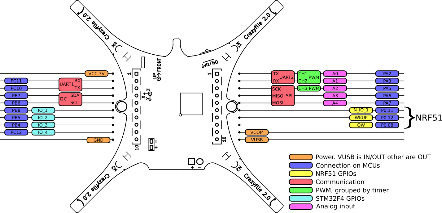
Expansion board template: The Crazyflie 2.0 expansion port template explained
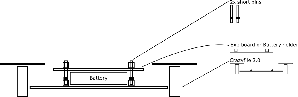
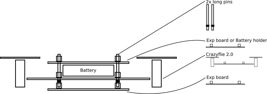
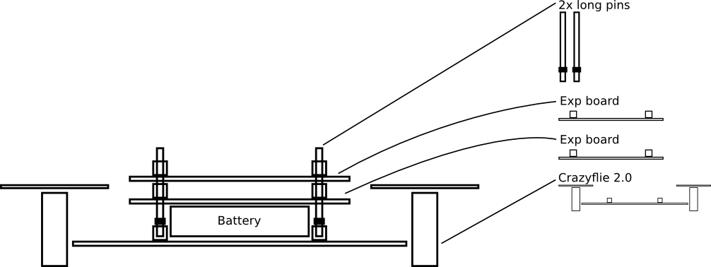
Expansion boards can be installed on top, bottom, or both top and bottom of the Crazyflie 2.0. The Crazyflie 2.0 and expansion board have female, pass-through connectors that can be fitted with male pins. Pins in two differing lengths exist to permit installation of either one expansion board on top, one board on bottom and one on top, or two boards on top. There should always be one expansion board or battery holder on top to secure the battery, unless the battery is held by other means (ie. rubber band, sticky pad, etc…).
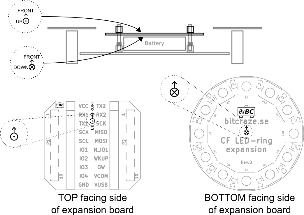
WARNING: It is important to install expansion boards in the right orientation. Installing a board in the wrong orientation might damage the expansion board and the Crazyflie 2.0.
All expansion boards display a logo describing the correct orientation:
For full specification see the datasheets of the NRF51 and the STM32F405
Expansion boards are detected by having a one-wire memory cabled on the OW pin. At startup memories are detected and read by the power management MCU, the nRF51822. If no incompatibility is detected the nRF51 starts the system and makes available the memories content to the application processor, the STM32F4, where the application code is running.
| VID | PID | ID | Name | Weight | Consumption | Mount location | Details page | Schematic |
|---|---|---|---|---|---|---|---|---|
| 0xBC | 0x01 | bcLedRing | LED-ring | 3.3g | 0 - 700mA | Below | link | link |
| 0xBC | 0x02 | bcQi | Qi charger | 5g | N/A | Below | link | link |
| 0xBC | 0x04 | bcBuzzer | Buzzer | 1.8g | 10mA | Below/Above | link | link |
| 0xBC | 0x05 | bcBigQuad | Big quad | 3.8g | N/A | Below/Above | link | link |
| 0xBC | 0x06 | bcDWM | UWB LPS | 3.3g | 160mA | Below/Above | link | link |
| 0xBC | 0x08 | bcUSD | Micro-SD | 1.7g | ~30mA | Below/Above | link | link |
| 0xBC | 0x09 | bcZRanger | Z-Ranger | 1.3g | ~15mA | Below | link | link |
| 0xBC | 0x0A | bcFlow | Flow | 1.6g | ~40mA | Below | link | link |
| 0xBC | 0x0B | bcOA | Obstacle Avoidance | N/A | ~0.3mA | Above | N/A | N/A |
| 0xBC | 0x0C | bcMultiranger | Multi-ranger | N/A | ~90mA (depending on mode) | Above | N/A | N/A |
| 0xBC | 0x0D | bcMocap | Mocap marker deck | N/A | 0mA | Above | N/A | N/A |
| 0xBC | 0x0E | bcZRanger2 | Z-Ranger v2 | 1.3g | ~15mA | Below | N/A | N/A |
| 0xBC | 0x0F | bcFlow2 | Flow v2 | 1.6g | ~40mA | Below | N/A | N/A |
| 0xBC | 0x10 | bcLighthouse4 | Lighthouse-4 | 2.7g | ~40mA | Above | N/A | N/A |
Below is a table showing which pins each deck uses. The table also contains information about boards that are not released yet, these are subject to change.
Assignments in parenthesis are unconnected but connectable via solder bridges or 0 Ohm resistors and are thus alternative connections. The idea is to make it possible to re-route a connection if you want to use two decks where the connections collide.
| UART1 | I2C | STM32 IO | UART2 | SPI | nRF51 IO | |||||||||||
|---|---|---|---|---|---|---|---|---|---|---|---|---|---|---|---|---|
| Name | RX1 | TX1 | SDA | SCL | IO1 | IO2 | IO3 | IO4 | TX2 | RX2 | CLK | MOSI | MISO | NIO1 | NIO2 | PWR |
| bcLedRing | PWM | PWM | VCOM | |||||||||||||
| bcQi | GHG | N/A | ||||||||||||||
| bcGPS | X | X | (PP)S | (RST) | (X) | (X) | (VBAT) | VCOM | ||||||||
| bcUSD | (CS) | (CS) | (CS) | CS | X | X | X | VCC | ||||||||
| bcDWM | IRQ | RST | CS | (IRQ) | (RST) | X | X | X | VCOM | |||||||
| bcBigQuad | (X) | (X) | (X) | (X) | X | X | (X) | X | X | (X) | (X) | (X) | N/A | |||
| bcBuzzer | PWM | PWM | N/A | |||||||||||||
| bcESP | (X) | X | X | N/A | ||||||||||||
| bcZRanger, bcZRanger2 | X | X | (X) | VCC | ||||||||||||
| bcFlow, bcFlow2 | X | X | (X) | X | X | X | X | VCC | ||||||||
| bcOA | X | X | VCC | |||||||||||||
| bcMultiranger | X | X | VCOM | |||||||||||||
| bcMocap | (X) | (X) | N/A | |||||||||||||
| bcLighthouse4 | X | X | X | X | N/A | |||||||||||
This table shows which deck that works on which platform.
| Crazyflie 2.X | Roadrunner | |
|---|---|---|
| LED-ring | yes | yes |
| Qi charger | yes | yes |
| Micro-SD | yes | *1 |
| UWB LPS | yes | |
| Big quad | yes | yes |
| Buzzer | yes | |
| bcESP | yes | yes |
| Z-Ranger, Z-Ranger V2 | yes | yes |
| Flow, Flow V2 | yes | yes |
| Multi-ranger | yes | yes |
| Mocap marker deck | yes | yes |
| Lighthouse-4 | yes | *2 |
This table shows which decks that can be used at the same time.
Note: This matrix is for unmodified decks and the standard firmware. Some decks can be modified to use other pins on the expansion port and thus work with decks that are marked as not compatible. Also decks that are normally physically blocking each other are marked as not compatible.
| LED-ring | Qi charger | Micro-SD | UWB LPS | Big quad | Buzzer | bcESP | Z-Ranger | Flow | Multi-ranger | Mocap marker deck | Lighthouse-4 | |
|---|---|---|---|---|---|---|---|---|---|---|---|---|
| LED-ring | yes | yes | yes | yes | yes | yes | yes | |||||
| Qi charger | yes | yes | yes | yes | yes | yes | yes | yes | ||||
| Micro-SD | yes | yes | *1 | yes | yes | yes | yes | *1 | yes | yes | yes | |
| UWB LPS | yes | yes | *1 | yes | yes | yes | yes | yes | yes | yes | *2 | |
| Big quad | yes | yes | yes | yes | yes | yes | *2 | |||||
| Buzzer | yes | yes | yes | yes | yes | yes | yes | yes | yes | |||
| bcESP | yes | yes | yes | yes | yes | yes | yes | yes | yes | |||
| Z-Ranger, Z-Ranger V2 | yes | yes | yes | yes | yes | yes | yes | yes | ||||
| Flow, Flow V2 | *1 | yes | yes | yes | yes | yes | yes | |||||
| Multi-ranger | yes | yes | yes | yes | yes | yes | yes | yes | yes | yes | yes | |
| Mocap marker deck | yes | yes | yes | yes | yes | yes | yes | yes | yes | yes | yes | |
| Lighthouse-4 | yes | yes | yes | *2 | *2 | yes | yes | yes | yes | yes | yes |
Notes: